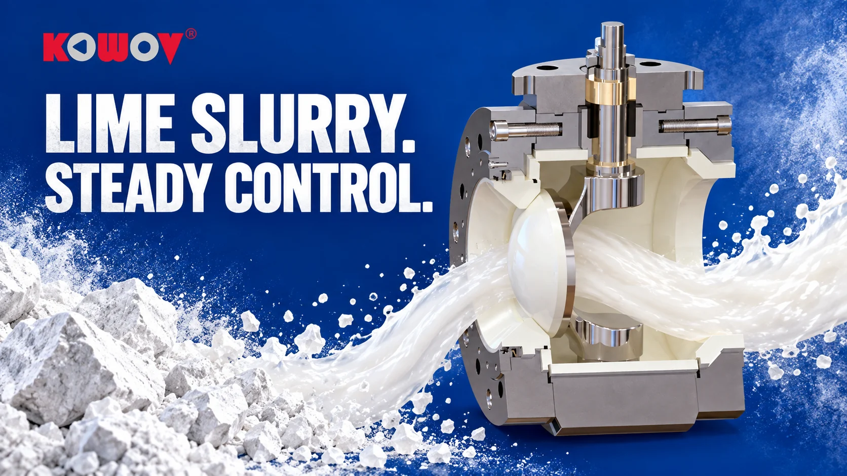
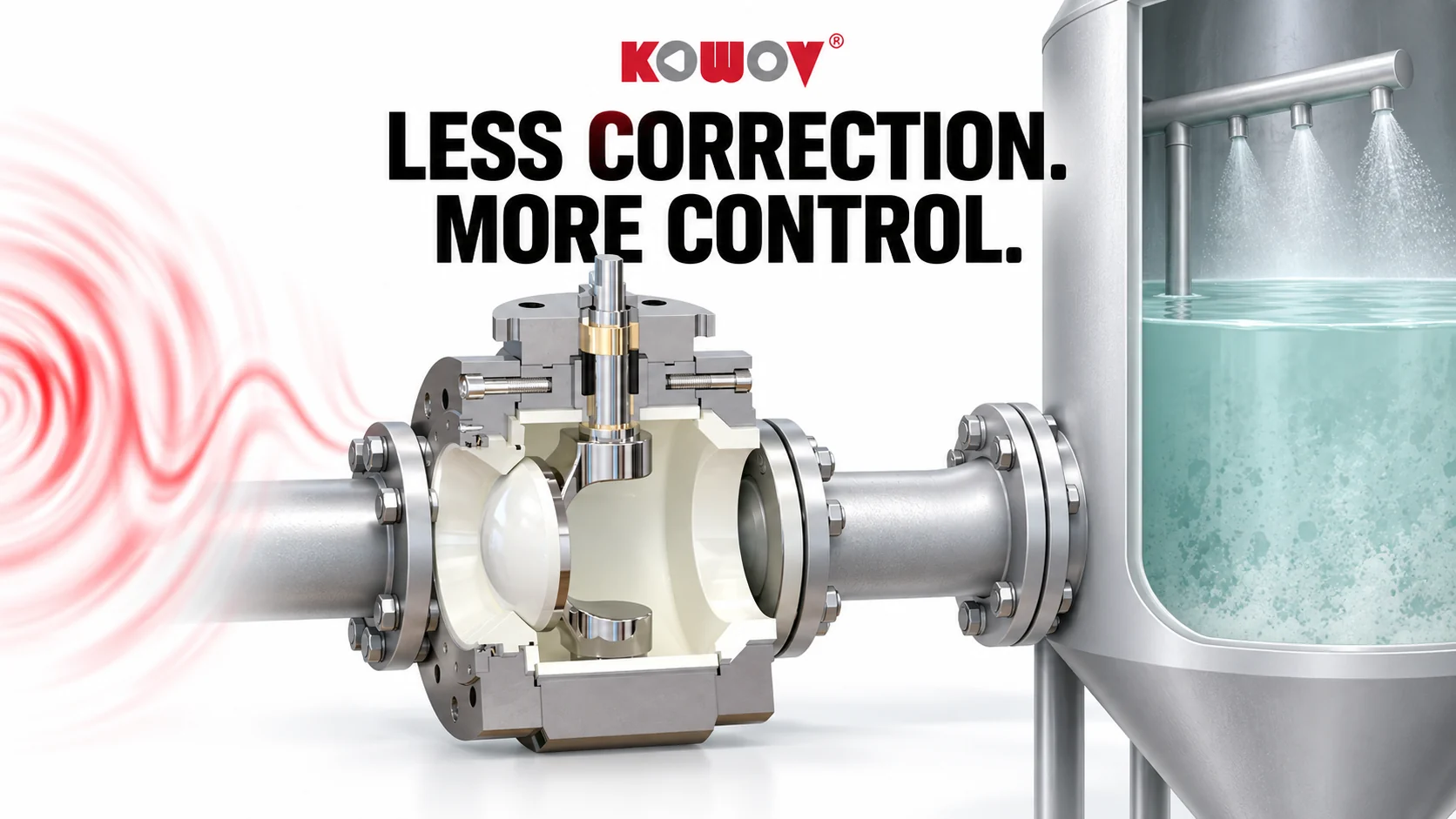
Inside a wet desulfurization valve duty
How slurry solids and corrosive media shape valve selection in a coal-fired power plant’s WFGD system
On this page
A DN100 limestone-slurry valve entered service in July 2008. Additional valves followed in December, then more positions in filtrate and process water. KOWOV's wet-desulfurization account describes an installation that expanded gradually as the plant gained operating experience.
The story is useful because it follows the service relationship over time. It also shows why “a desulfurization valve” is too broad a description for selection.
Different streams within one absorber system
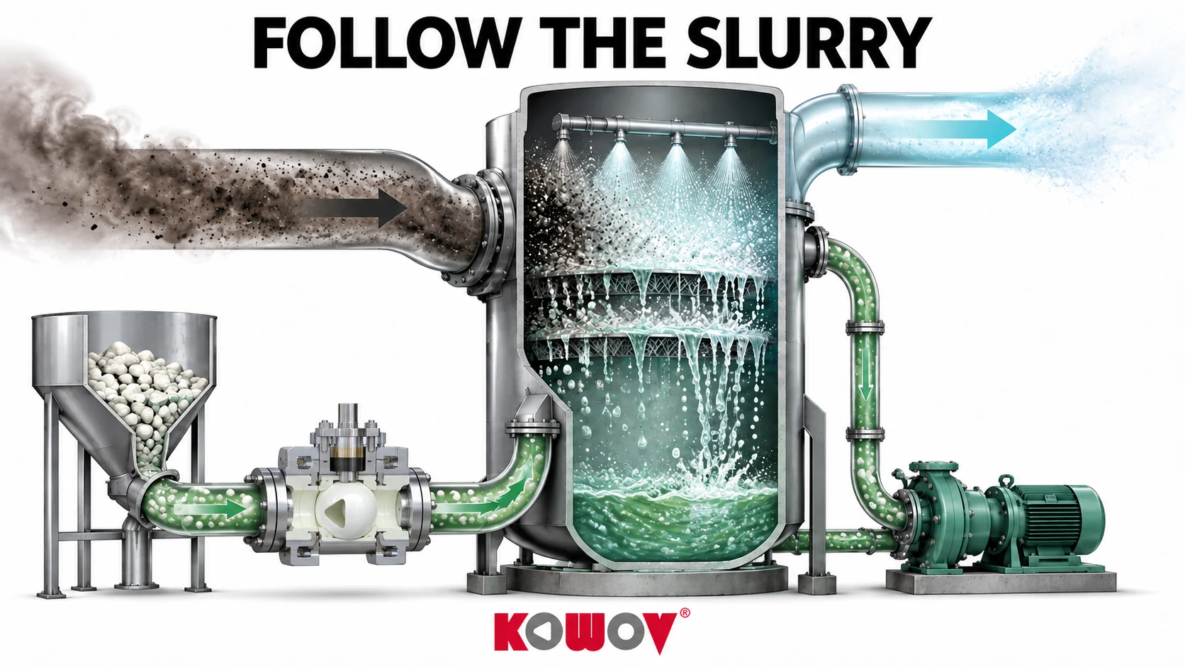
Wet flue gas desulfurization brings gas into contact with an alkaline slurry. The associated piping includes slurry feed, recirculation, drains and water services. Solids loading and chemistry differ between those positions.
Particles can erode a restricted passage or damage a sealing surface during movement. The liquid chemistry may also attack exposed materials. Where a valve regulates, its normal opening range affects which surfaces see the concentrated stream.
A replacement assessment should therefore identify the stream and function. A water isolation valve and a slurry control valve may need different construction and acceptance criteria even when they are installed near each other.
The plant's first KOWOV trial
The original account describes engineers investigating alternatives in May 2008 after unsatisfactory valve service. KOWOV brought samples and discussed the material and sealing arrangement with the plant.
The first DN100 valve was installed for limestone slurry in July. Four additional valves of the same specification were ordered in December 2008. In January 2009, ceramic ball valves were also introduced for filtrate and process-water positions.
The report identifies high-strength zirconia components and a compensation arrangement as parts of the construction reviewed at the time. A current selection still needs the exact model and material schedule for the proposed duty.
Expansion and later maintenance
By December 2013, the account records nearly eighty KOWOV valves, ranging from DN50 to DN150, at the plant. It then describes a period without additional valve purchases from 2014 to 2021, followed by requests for spare parts and further units.
A purchasing gap is evidence about orders, not a complete maintenance log. It should not be read as proof that every installed valve operated untouched for that entire period. The continuing spare-parts relationship is part of the service history.
For an engineering comparison, the most useful next layer is the record by position: installation date, inspected condition, packing or trim work and the reason for eventual replacement.
Choose the current construction by duty
The FCCV1 ceramic ball valve provides a starting point for suitable abrasive and corrosive service. The FCRV ceramic C valve is relevant where deposits and regulation need a different geometry.
Provide the slurry composition, solids size and concentration, temperature, flow range and both pressure readings. Include the required leakage acceptance and any history of deposits, sticking or actuator problems.
The historical power-plant overview places this case alongside other KOWOV applications. For a new project, use the detailed local duty to choose the product and the inspection plan.
Discuss your application
Match the valve to the specific slurry or water position in your FGD system